
Preparing a 3D Model for Robotic Welding
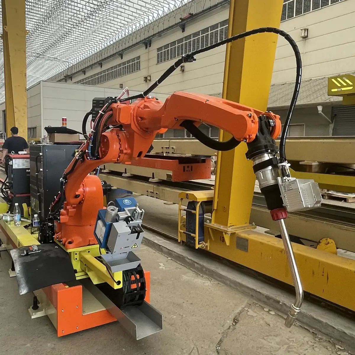
In the model-based workflow, software reads the component model, extracts weld information and plans the robot’s path. The result depends on how closely the model matches the part that arrives at the welding station.
What the Model Is Used For
The model supplies geometry for weld extraction, welding-parameter matching, path planning and collision checking before the path is sent to the robot. On the 7-axis station, each seam is also scanned for positioning before welding.
Model the Assembled Condition
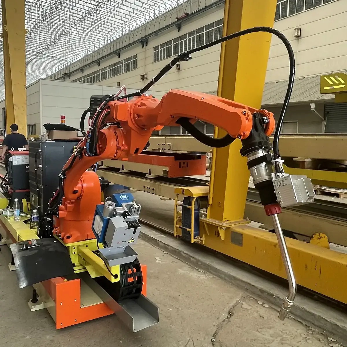
Model the part as it is assembled for welding, including stiffeners, brackets, end plates and other attachments. A drawing of the finished member is not enough if the fit-up at the welding stage differs from it.
Fixtures and temporary supports present during welding are part of the working space. Note them even when they are absent from the finished component.
Keep the Model and Fit-Up in Step
Changes made on the shop floor, such as a moved attachment or a different plate, need to be reflected in the model before welding. Normal fit-up photos help identify differences between the model and the actual part.
Consistent assembly and visible seams support the scanning and seam-location steps of the workflow.
Weld Information to Prepare
| Item | Why it matters |
|---|---|
| Joint type and location | Defines which welds are extracted and the path that is planned |
| Weld size and required welding procedure | Determines welding parameters and whether the task suits the station’s welding package |
| Material and plate thickness | Affects parameter matching; thickness uncertainty needs operator attention |
| Surrounding steelwork | Shows where the torch approach may be restricted |
Detailing Software and File Formats
The station imports STEP and IFC models. Models produced in structural detailing software such as Tekla Structures are commonly exported to IFC. Send a sample model with your inquiry so it can be checked before the project starts.
When There Is No Model
No model is needed to start an inquiry. For welding, the scan-based reverse modelling route is currently limited to flat web plates with stiffeners, and prepared nodes suit recurring, open details that match a node developed in advance.
Scan-Based Reverse ModellingRead the welding robot FAQMore welding robot guides
Send a Representative Model or Drawing
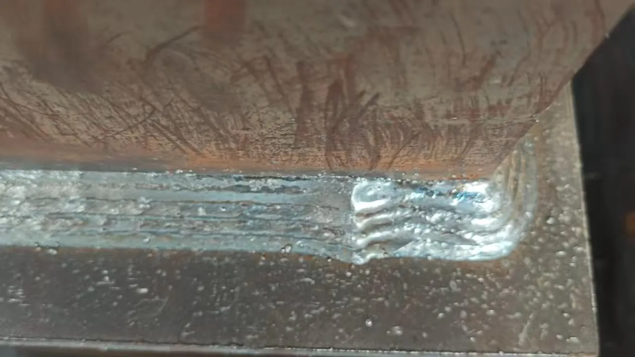
Share a drawing, model or photo of a typical part and describe the welds you want to automate. Files are optional for the first message.
Or email [email protected]