Honglu Steel Structure Email Honglu
Menu

Bridge and wide-planar application

Bridge Steel Welding Robot Evaluation

Evaluate bridge steel, plate-unit diaphragms and other wide planar workpieces through a project-specific review for the 8-Axis Cantilever Welding Robot.

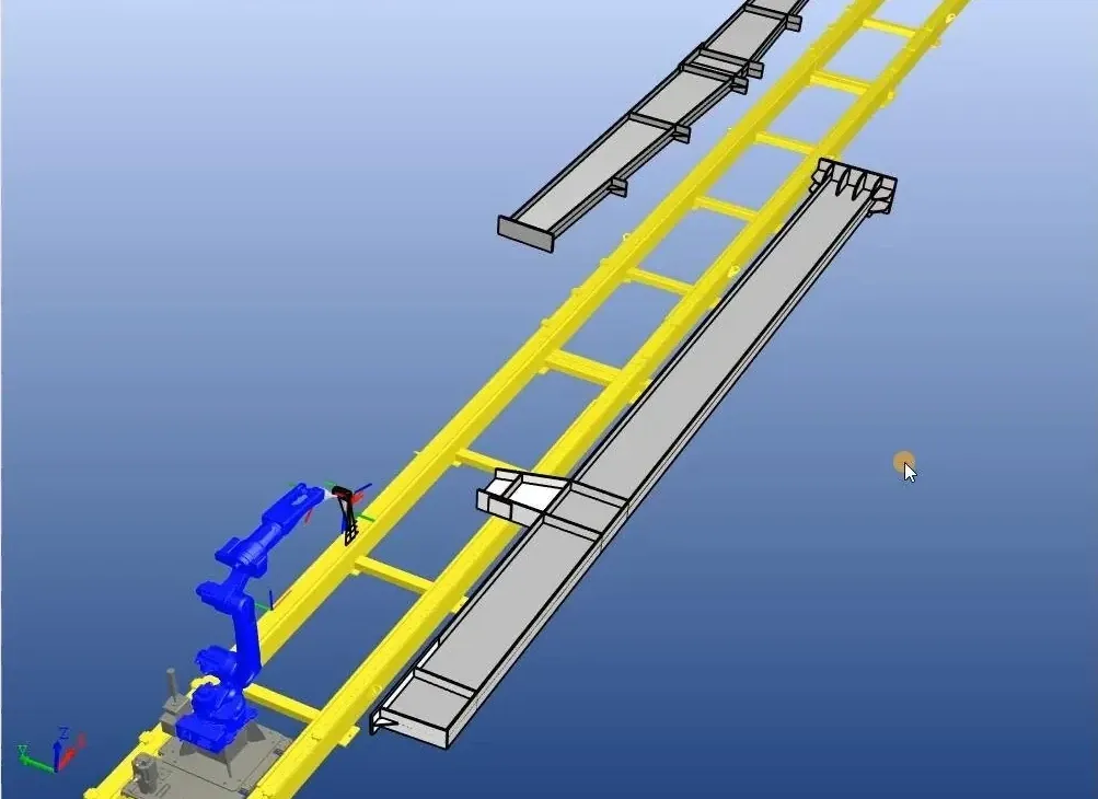
CAD illustration of an eight-axis cantilever welding robot workstation. CAD illustration
CAD illustration, not a photograph; work envelope, external axes and final configuration require project review.

Workpiece first

Begin with a representative bridge component

A bridge steel project starts with actual geometry, joints, weld positions and access—not a standard machine label.

Provide one typical workpiece that represents normal production and one example that shows the most difficult detail. Include overall drawings, local sections and weld symbols for both.

If several families share the line, list their dimensional and joint differences. This separates repeatable work from exceptional parts that may need another setup or route.

Fit versus evaluation

A category match is only the first step

The documented application direction supports engineering evaluation while specific suitability remains conditional.

Workpiece categories

Prepare each bridge family for review

Use separate drawings when one component cannot represent the complete production range.

01

Plate-unit diaphragms

Show plate arrangement, diaphragm orientation, stiffeners, openings, surrounding obstructions and which joints are prepared before loading.

02

Wide planar components

Submit cross-sections and local details where ribs, brackets, cut-outs or fixtures affect the approach path or workpiece support.

03

Plate girders

Treat the inquiry as drawing-led. Provide web and flange geometry, transverse details, splice areas, attachments and required weld positions.

Engineering inputs

Connect geometry, joint definition and torch access

A visible seam is not automatically reachable when the required approach, cable path or surrounding clearance is restricted.

Geometry and datum

Submit overall dimensions, local sections, drawing datum and workpiece orientation at loading. Show fixtures, supports and temporary members that occupy the approach area.

Joint definition

List joint type, preparation, weld size, pass requirement and acceptance basis. Separate continuous seams from short joints, intersections and interrupted areas.

Weld position and access

Mark the intended position and preferred orientation. Provide local clearance around ribs, plates, brackets and fixtures, including difficult start and end points.

Production and site

Explain the loading method, support height, production sequence, aisle limits, nearby equipment and whether the workpiece changes orientation.

Eight-axis direction

Define the cantilever arrangement from the project

The 8-Axis Cantilever Welding Robot is the Honglu evaluation direction for the bridge and wide-planar workpieces described here.

The cantilever structure does not establish a universal dimensional promise. Configuration follows the workpiece layout, required motions, loading method and site arrangement.

Review the 8-Axis Cantilever Welding Robot page for the product direction, then use this application checklist to prepare the bridge-specific inputs.

Envelope limits

Keep axes, coordinates and coverage under review

Do not estimate usable coverage from a CAD view, robot reach, rail length or machine-body dimension.

  • Define axis directions and coordinated-motion relationships.
  • State the reference coordinates and measurement datum.
  • Confirm clearance for the actual workpiece and cell layout.
  • Show loading space, supports and restrictions near the equipment.
  • Use a formal project work-envelope drawing before configuration.

Workflow

Connect the digital route to the bridge workpiece

The workflow follows the supplied model, joint information, assembly state and difficult local details.

A model-driven discussion can include geometry interpretation, planning and collision checking when usable data is available. No-Model and Node-Based routes have narrower documented conditions and retain preparation and human-review requirements.

Compare the workflow paths and required inputs.

Application context

Interpret factory and CAD visuals carefully

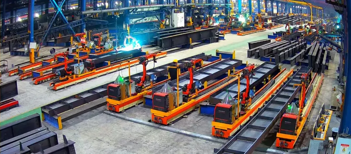
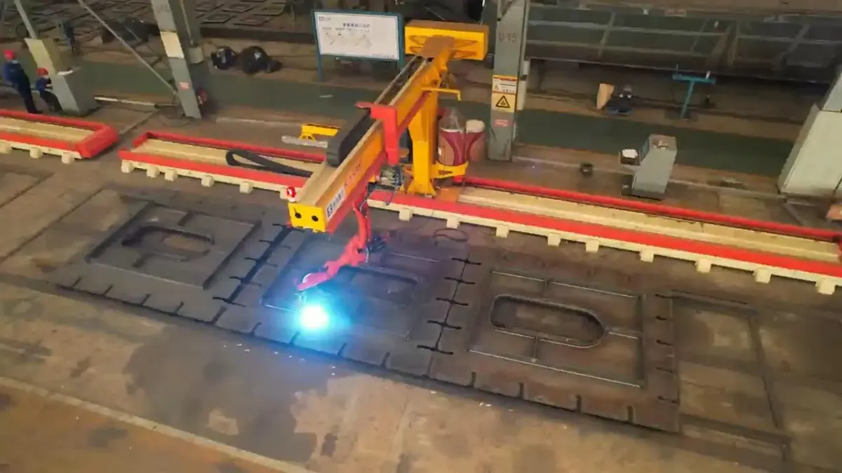
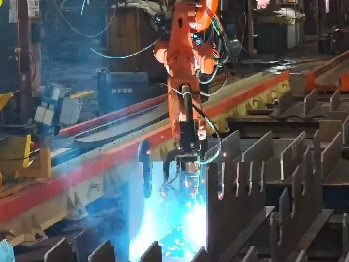
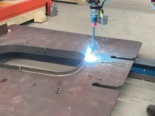
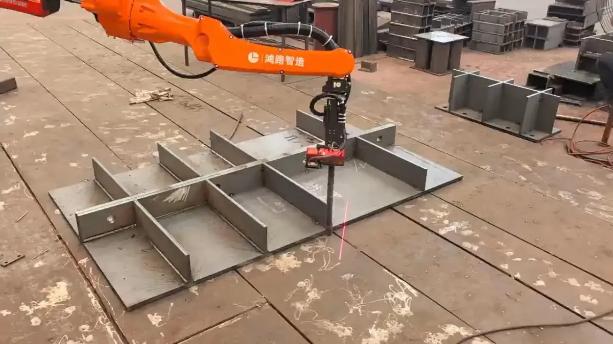
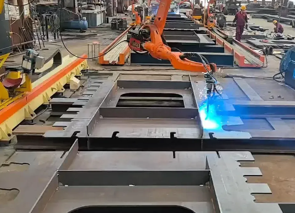
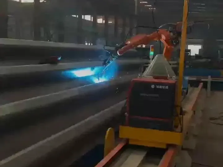
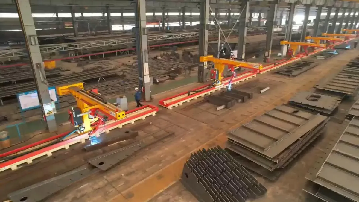
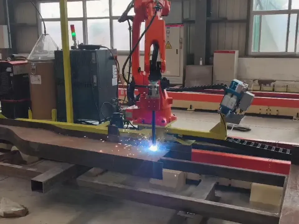
Honglu domestic production-base scenes show internal application context, not overseas customer installations.

A photograph supports only what is visibly present. A CAD illustration explains arrangement when labeled accurately, but it cannot establish hidden configuration, performance, dimensions or suitability for another project.

Project inputs

What to send for a bridge welding evaluation

Send the most representative information first if the complete package is not yet available.

  • Overall drawings with dimensions, sections, datums and coordinate directions.
  • Three-dimensional models when available, including format and revision status.
  • Weld maps with joint type, preparation, weld size, passes and positions.
  • Local details for diaphragms, stiffeners, brackets, openings and restricted areas.
  • Photos of fit-up, fixtures, supports and the intended loading condition.
  • Production mix, important workpiece variations and relevant project requirements.
  • Site layout, loading method and available space around the proposed cell.

Project evaluation

Request the next bridge engineering step

Connect the representative workpiece, weld requirements and site layout with an appropriate robot direction.

The website inquiry mailbox receives and routes your message. Your inquiry will be reviewed by Honglu’s engineering and commercial teams. Project scope and commitments are confirmed in reviewed project documents and quotations.