
Every member is different
No programming per member
Import the model and the software plans every weld. One-off members weld as easily as repeat ones.
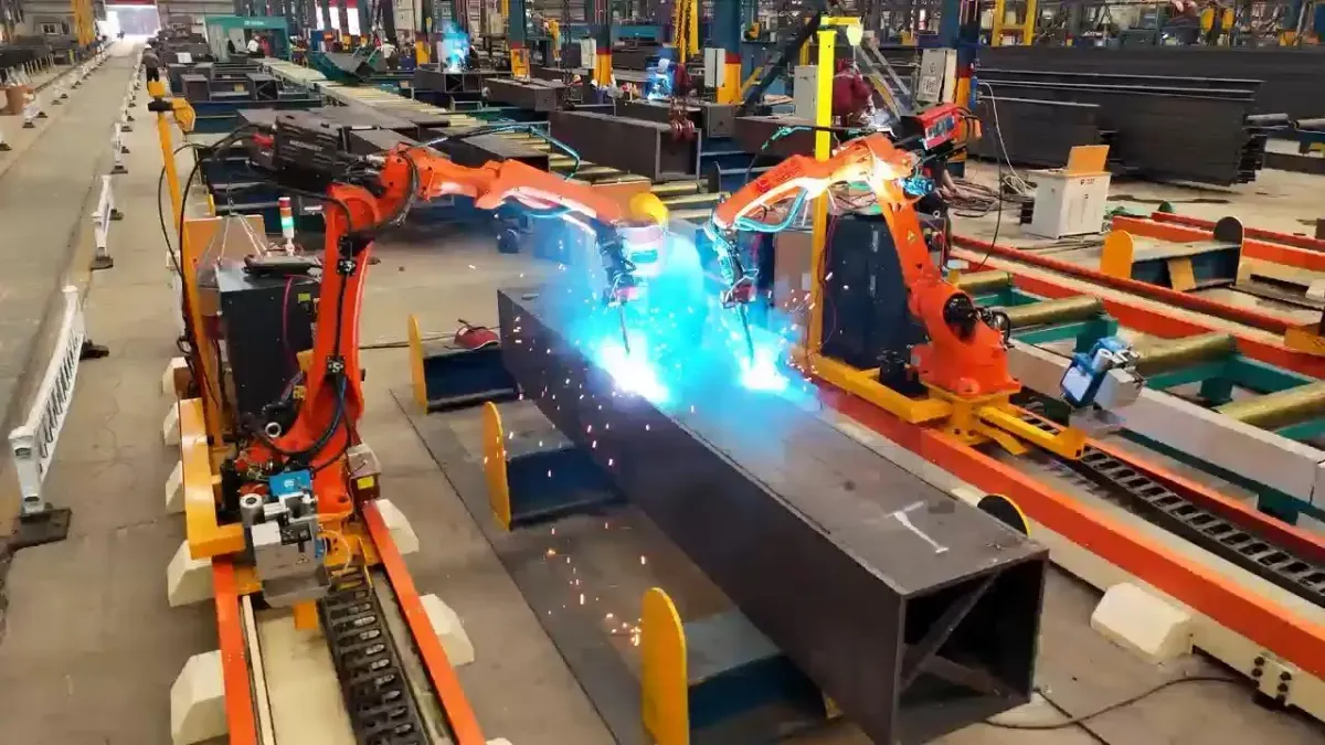
Robotic beam and column welding
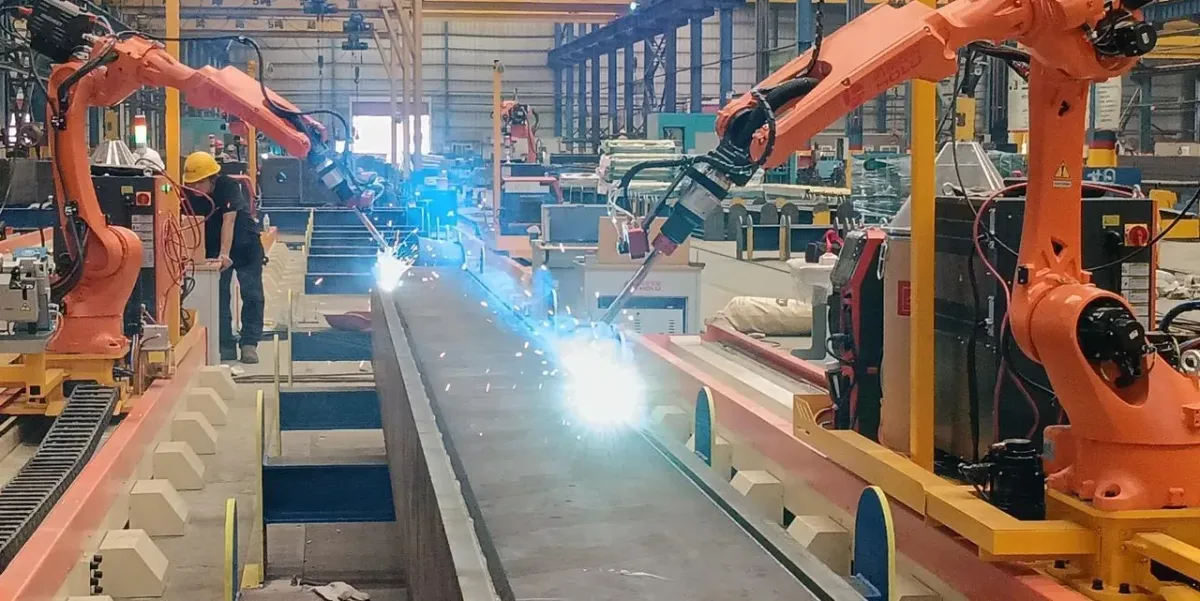
H-beams (I-beams), columns and crane runway beams carry dozens of stiffeners, end plates, corbels and cleats — short welds in every direction that are slow and tiring to weld by hand. Our rail-mounted robot welds them straight from your 3D model.
Every member is different
Import the model and the software plans every weld. One-off members weld as easily as repeat ones.
Many short welds per member
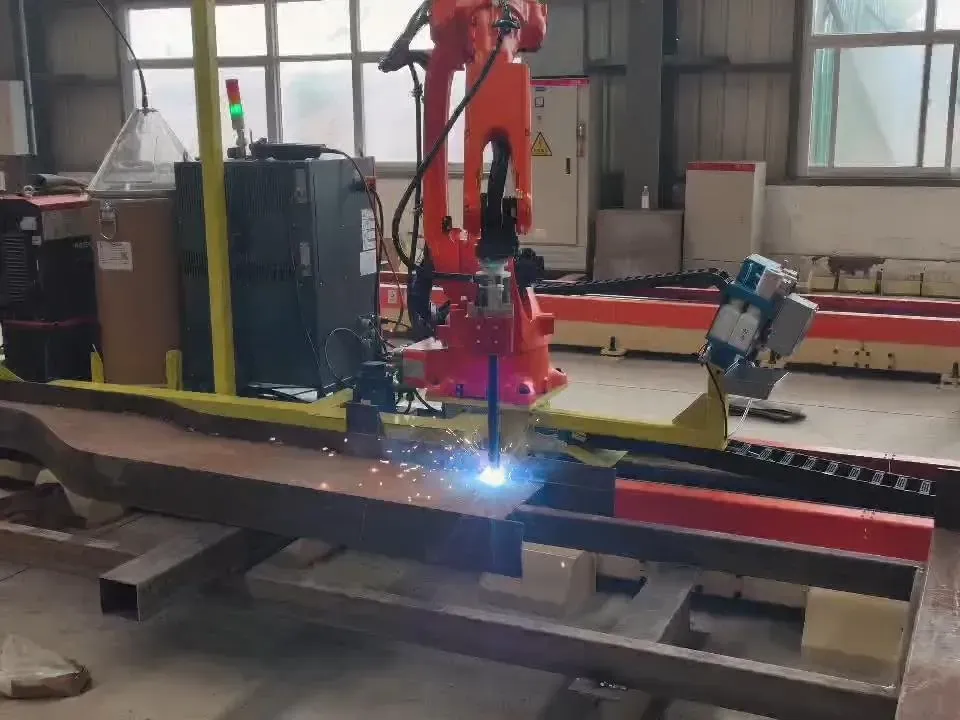
The robot moves along the rail and welds stiffeners, end plates, corbels and cleats along the member.
Skilled welders are scarce
Each robot welds 70–120 m per day shift, and operators learn to run the station in 1–5 days.
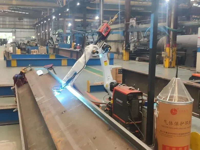
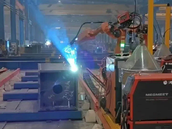
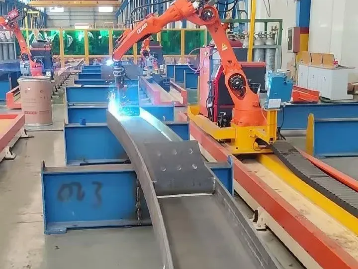
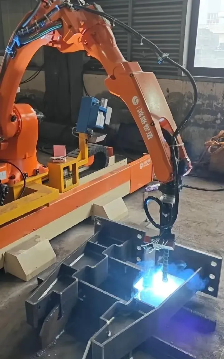
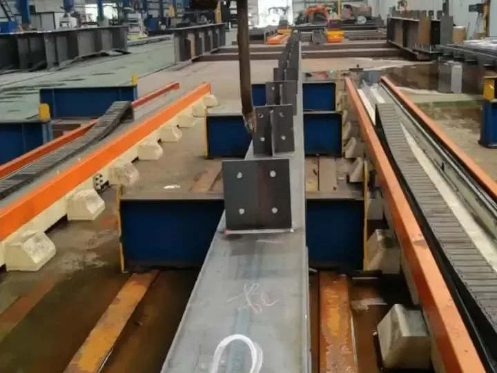
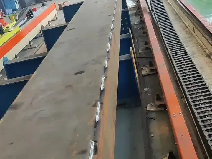
What the 7-axis robot welds on a typical member.
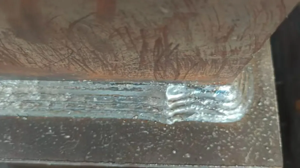
Torch access decides what is reachable: flat welds between stiffeners need about 150 mm of clearance for a standard torch.
| Weld | Where you find it | Robot |
|---|---|---|
| Straight fillet welds | Stiffeners, end plates, web-to-flange | Flat (PA) and horizontal (PB) |
| Vertical fillet welds | Stiffeners and end plates | Vertical down (PG) |
| Polyline and curved welds | Corbels, brackets, curved beams | Yes |
| Wrap-around welds | Stiffener ends | Yes |
| Lap welds | Cleats and lapped plates | Yes |
| Intermittent welds | Long secondary seams | On straight seams |
| Large fillets (leg over 10 mm) | Heavy members | Several passes |
See the 7-axis rail-mounted robotWelding PEB columns, rafters and fittingsGantry welder and robot in an H-beam line
Tell us what you weld. Drawings and models are welcome but not required to start.
Prefer email? sales@steelweldingrobot.com
Common questions about robotic beam and column welding.
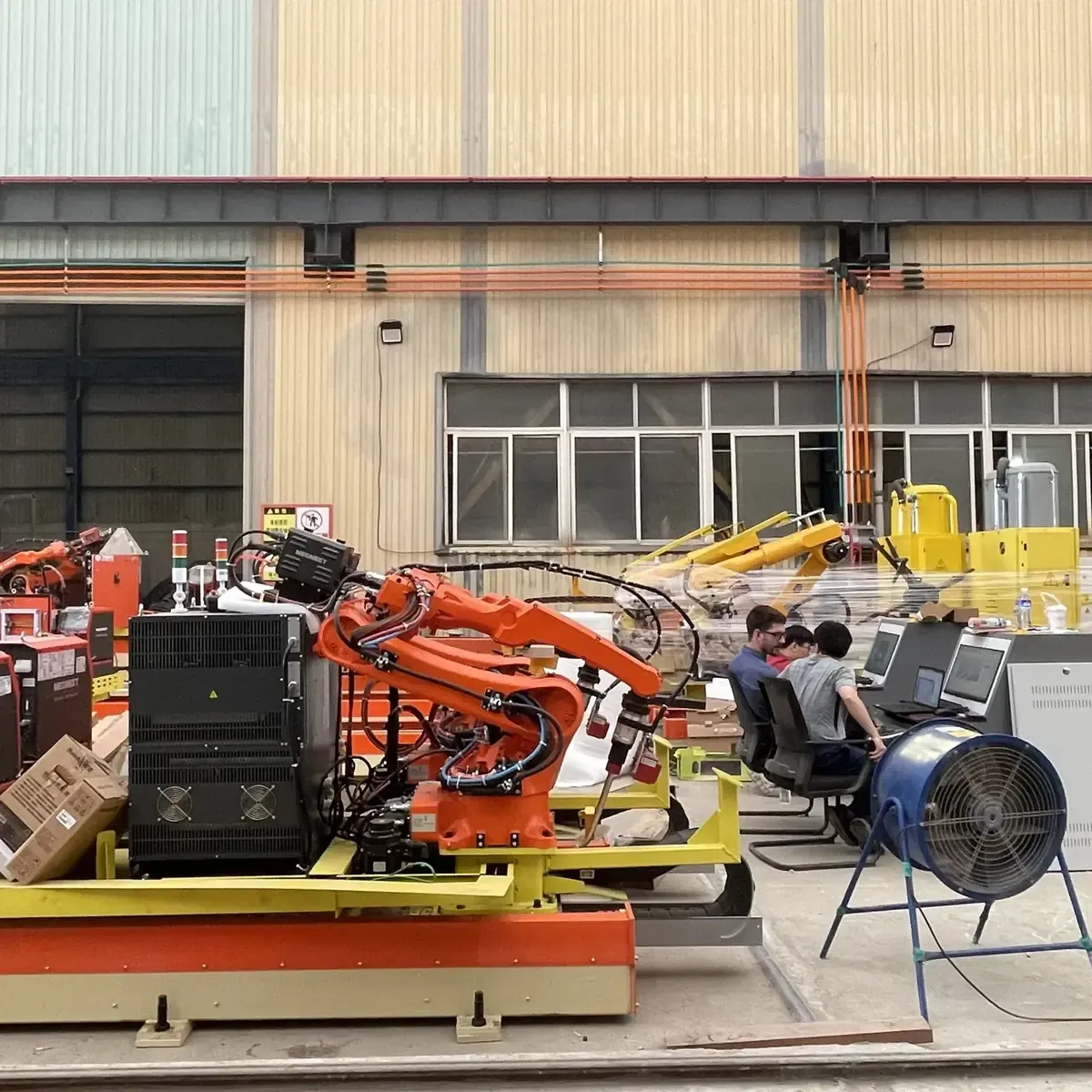
Members up to 1,500 mm wide. The standard rail is 12 m long with 10.63 m of effective travel; tell us your longest members and we check the layout.
An H-beam welding machine welds the long flange-to-web seams of straight beams. The robot welds what is fitted afterwards: stiffeners, end plates, corbels and cleats.
Yes, the rail-mounted robot welds box beams and columns with gas-shielded welding. For full-penetration seams on box columns we also offer a submerged arc station.
Sometimes. Flat welds between stiffeners need about 150 mm of clearance for a standard torch. The free evaluation shows which welds the robot takes and which stay manual.
Flat web plates with stiffeners can be scanned at the station. Other members need a STEP or IFC model, which Tekla and most detailing software can export.
Send a drawing, model or photo of a typical member. Our engineers check which welds the robot can take and recommend a station — free of charge. We reply within one business day.
Or email sales@steelweldingrobot.com