
No programming per part
A part with a model is ready to weld once it is loaded. There is no teach pendant work and no robot programmer.
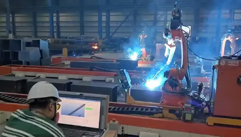
From 3D model to weld path
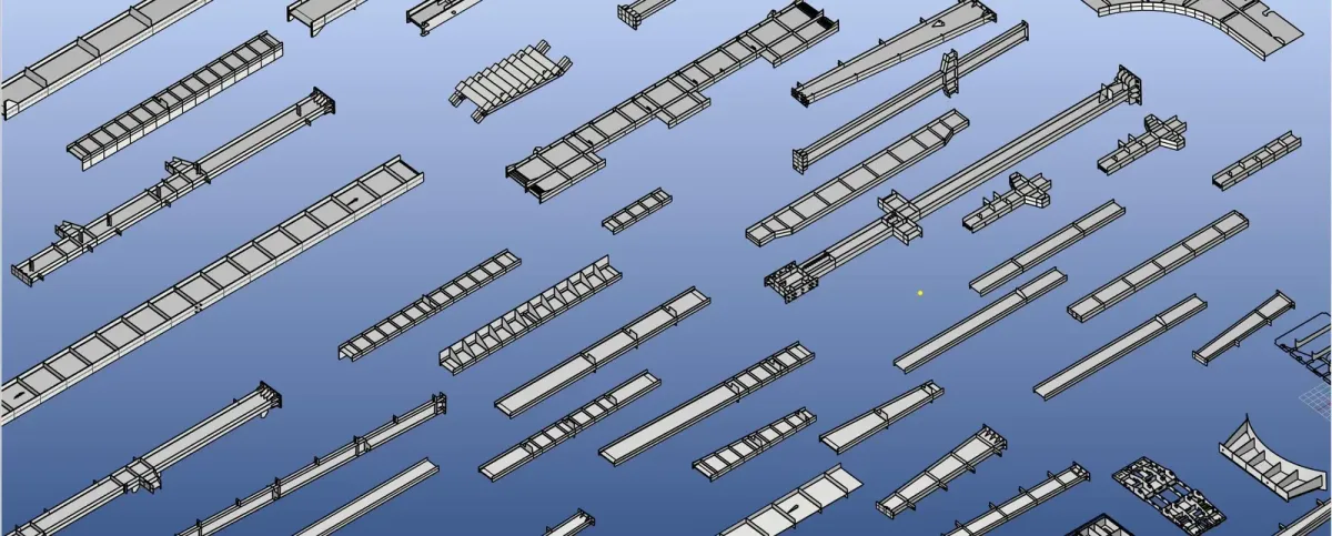
A conventional welding robot has to be taught point by point for every new part — which rarely pays off for one-off structural steel. Our software reads your 3D model instead: it finds the welds, plans the path and checks it for collisions.
Software and robot controller are developed in-house, with 3D vision developed for our stations.
A part with a model is ready to weld once it is loaded. There is no teach pendant work and no robot programmer.
Mixed beams, columns and plates can be welded in batches of one, because nothing has to be taught.
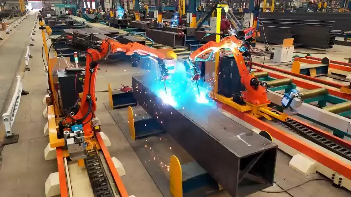
Operators load parts and start jobs. They learn to run the station in 1–5 days, and one operator runs 3–6 stations.
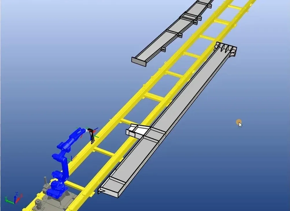
Every path is simulated in a 1:1 3D model of the station and checked for collisions before it reaches the robot.
Load a STEP or IFC model, or scan the QR code on the part label to fetch it.
The software finds the welds and takes parameters from a structural steel process library.
Paths are planned and checked for collisions in a 1:1 simulation, which also estimates cycle time.
A laser line scan finds the part on the station, so welding can typically begin 2–3 minutes after loading.
Each seam is scanned before welding and followed with arc tracking; the welded length is logged.
The main route for parts with a 3D model — the model already holds the geometry the robot needs.
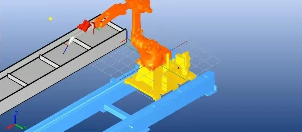
For flat web plates with stiffeners, the station scans the part with its laser line scanner and builds the model itself — no drawing needed. The same camera handles both model-based and scan-based work.
The cantilever station also supports parametric modelling: enter the dimensions of a standard part and the software builds it.
Scan-based modelling works on flat, stiffened plates with visible surfaces. Other shapes need a 3D model.
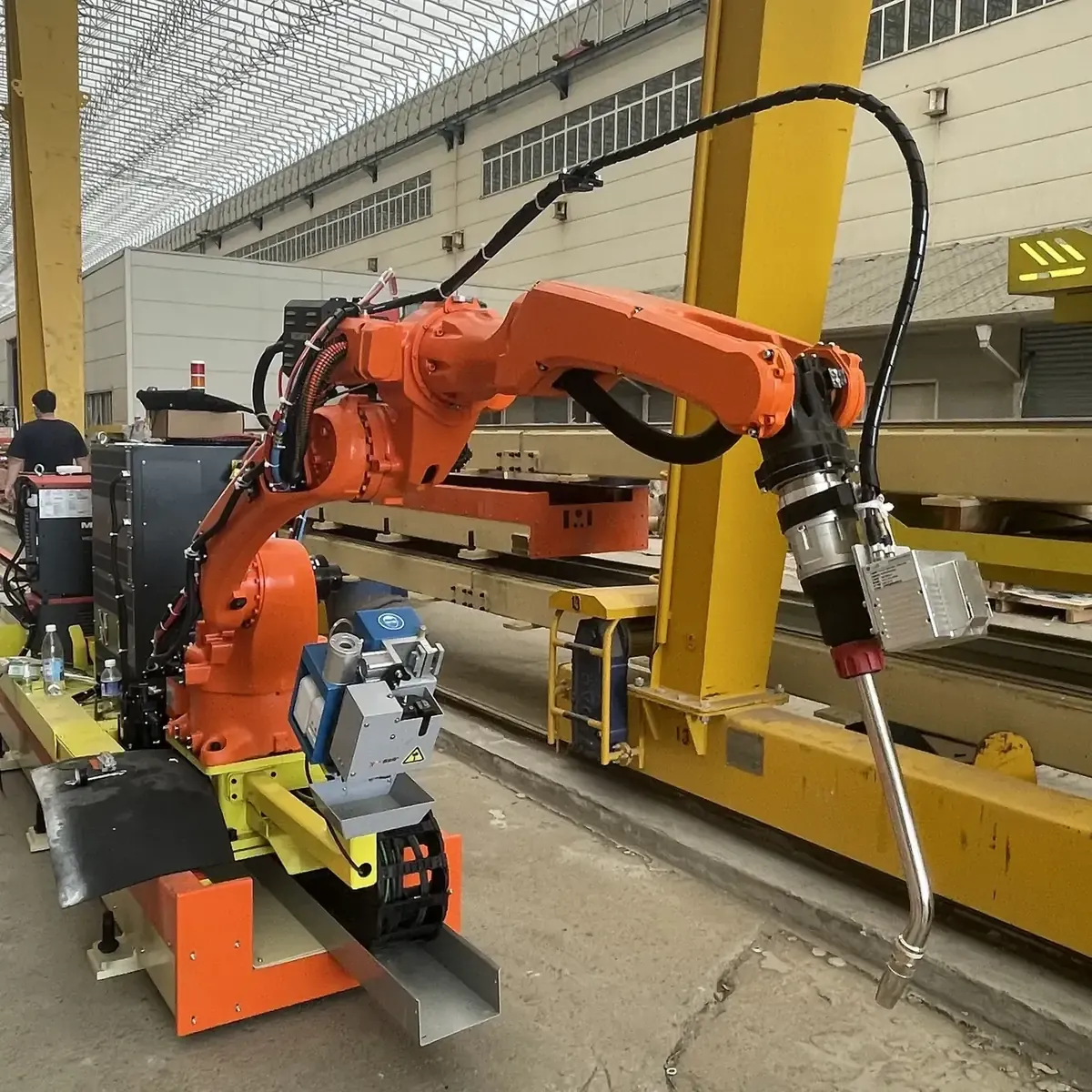
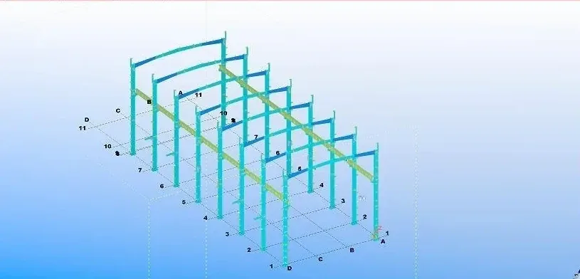
From the building model to the weld path, every step happens before the robot moves.
The welding process library draws on data from the 2,000+ robots running in our parent company’s plants.
Software updates are free for the life of the station.
Prepared nodes suit recurring details. The node is developed in advance; the operator selects it, sets the parameters and checks the clearance. A new detail needs its own node first.
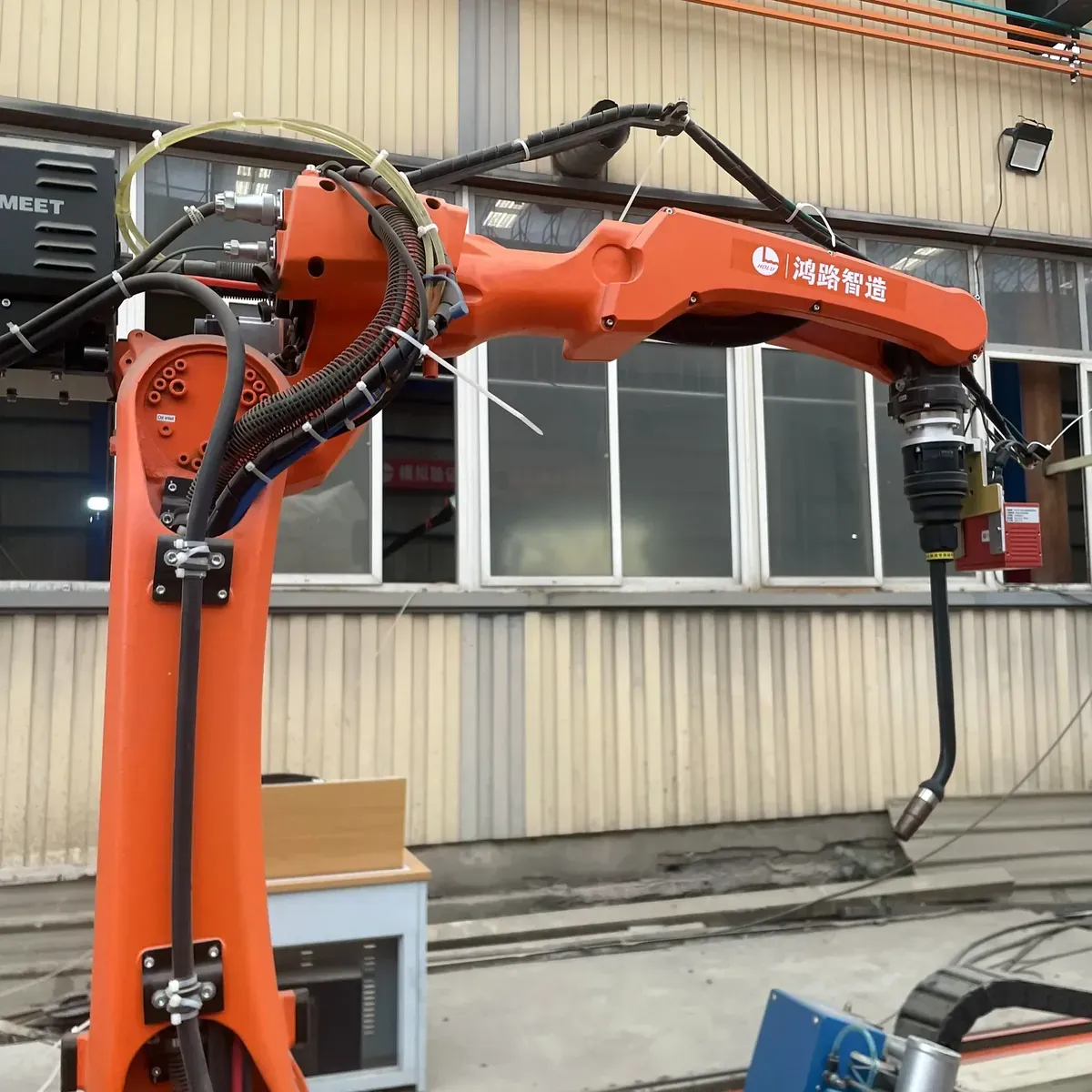
Simple teach mode is kept on every station for narrow spaces, unusual welds and touch-ups — with an easier interface than a conventional teach pendant.
An optional remote control lets the operator trim torch position up, down, left and right, as well as current, voltage and weaving amplitude, during welding.
| Route | Best for | What you provide |
|---|---|---|
| Model-based | Beams, columns and assemblies with a 3D model | A STEP or IFC model matching the assembled part |
| Scan-based | Flat web plates with stiffeners | The part itself, loaded on the station |
| Parametric (cantilever) | Standard plate parts | The part dimensions |
| Prepared nodes | Recurring details | A detail matching a prepared node |
| Simple teach | Narrow spaces, special welds, touch-ups | Operator teaching of a few points |
Common questions about programming our welding robots.
The robot path comes from the 3D model instead of being taught point by point with a pendant. The operator loads the job; the software plans and checks the path.
STEP and IFC. Tekla Structures and most other detailing software export IFC. If you use Tekla Structures, we provide a free plug-in that exports a whole project's IFC models in one batch.
It should match the assembled part. Before each weld the robot scans the seam to find its actual position, and parameters come from the process library.
Flat web plates with stiffeners can be scanned at the station. Other parts need a model — you do not need one to send a first inquiry.
Yes, as an option. Jobs can be loaded by QR code, and welded length is reported for each part for production statistics.
The station also supports full teach programming with a screen-equipped pendant. With quick teach, the operator marks only the seam start, end and transition points; the robot takes the welding parameters from the process library, so no parameters need to be set by hand.
Send a STEP or IFC model, a drawing or a photo of a typical part. Our engineers check which welds the robot can take and recommend a station — free of charge. We reply within one business day.
Or email sales@steelweldingrobot.com