Long beams and columns
7-axis rail-mounted
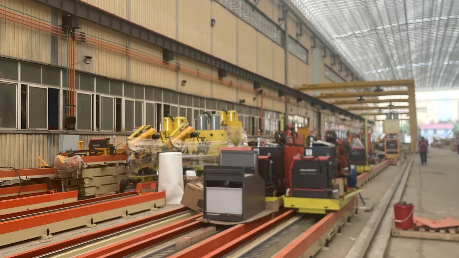
The robot travels beside the member and welds along its length.
 STEEL WELDING ROBOTS
Buyer’s guide
A welding robot arm has six axes. Every axis beyond six is an external axis — usually a rail or cantilever that carries the arm — and it decides how far the robot can reach. Here is what each configuration means for structural steel, and how to choose.
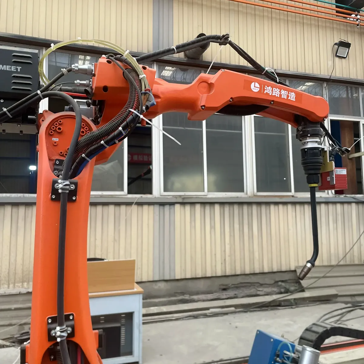
Axes 1–6 are the robot arm: base rotation, shoulder, elbow and three wrist joints. Together they place the torch at the joint and set its angle. Our welding robot arm reaches about 2 m and can be mounted upright or upside down.
Axes 7, 8 and 9 move the whole arm: along a ground rail, with a cantilever or on a gantry. They extend the working range from the arm’s own reach to the full length and width of the part.
So the axis count tells you how the robot moves. The question for your workshop is whether that movement reaches the welds on your parts.
| Configuration | How the robot moves | Typical structural steel parts |
|---|---|---|
| 6-axis, fixed base | The arm stands in one place; parts are brought to it, often on a positioner. | Small parts and sub-assemblies within the arm’s reach. |
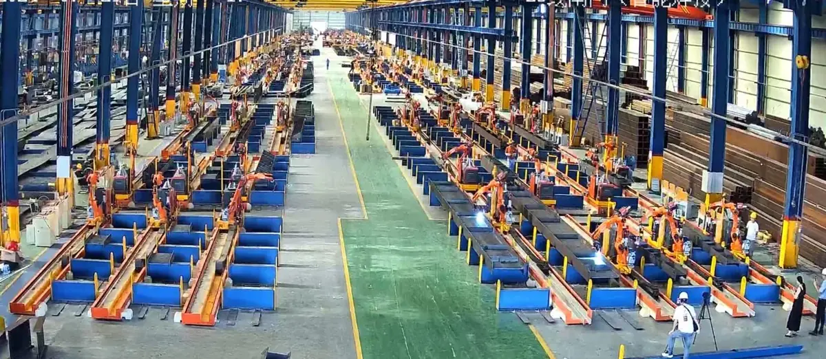
| 7-axis, ground rail | The arm travels on a rail beside the part. | H-beams, columns and crane runway beams up to 1,500 mm wide, on a 12 m rail as standard. A submerged arc version welds full-penetration seams on box columns. |
| 7-axis, cantilever | The arm hangs upside down from a cantilever that travels along the station. | Parts that need an approach from above, within a single travel axis. |
| 8-axis, cantilever | The arm hangs upside down from a cantilever that travels along the station. | Bridge plate units, diaphragms and wide plates up to 3,500 mm wide. |
| 9-axis, cantilever | The arm hangs from a cantilever that moves along a 9 m rail, 2.5 m across and 2.5 m up and down (standard). | Equipment frames, box structures and transformer tanks; also parts without drawings, captured by a large line scanner. |
| Gantry | One or two robots hang beneath a frame that spans the work area. | Twin-robot and multi-robot layouts, with the part beneath the frame. |
See the submerged arc welding robot
Configurations describe our product range. Final travel and working range are confirmed in your proposal.
Long beams and columns
The robot travels beside the member and welds along its length.
Wide plates and bridge units
The robot works across the full width of the plate from above.
Frames and box structures
An inverted cantilever layout for three-dimensional frames and box structures.
Small parts
A compact station for parts that fit within the arm’s reach.
See the 7-axis rail-mounted robotSee the 8-axis cantilever robot
Each extra axis adds reach and flexibility, but also structure, floor space and cost. A 9-axis station is not a better 7-axis station — it is built for a different kind of part.
Choose the configuration that reaches the welds on your parts with the least equipment. Stiffeners, brackets and torch angle matter as much as the axis count.
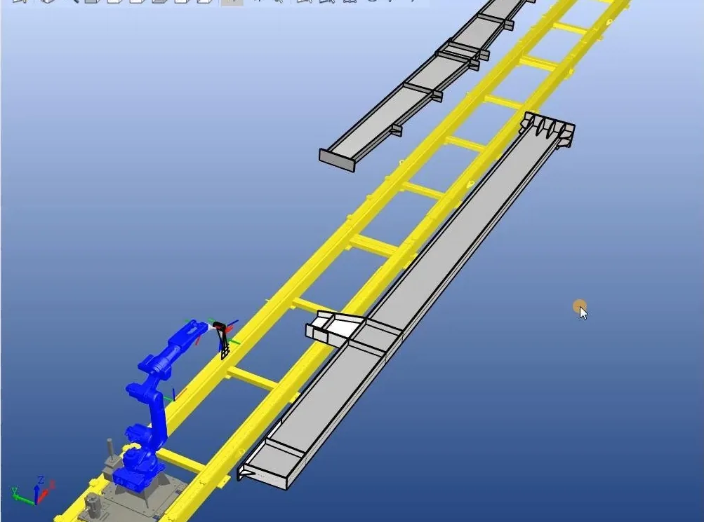
Standard stations use a 12 m rail (10.63 m effective travel) for the 7-axis robot and a 15 m frame (12 m effective travel) for the 8-axis robot. The range of motion can be adapted to your parts — tell us your longest and widest components.
Two robots can also share one rail for long members.
Common questions about welding robot axes.
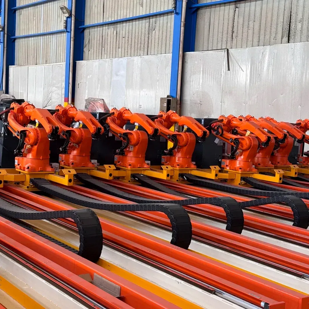
A six-axis robot arm on a seventh, linear axis. On our ground-rail station the rail carries the arm along long beams and columns; we also build a 7-axis cantilever version that works from above.
Not for beams and columns. The 9-axis layout adds movement across and up and down (2.5 m each as standard) for three-dimensional frames and box structures; a 7-axis rail station suits long members with less equipment.
About 2 m (2,014 mm). The rail or cantilever extends this to the full length and width of the part.
The range of motion can be adapted to your parts. Tell us your longest and widest components and we recommend a layout.
Send a drawing, model or photo. Our engineers recommend a configuration free of charge.
Send a drawing, model or photo of your longest and widest parts. Our engineers recommend a configuration and quote it — free of charge. We reply within one business day.
Or email [email protected]