
Rail-Mounted, Cantilever or Gantry: Choosing a Welding Robot Layout
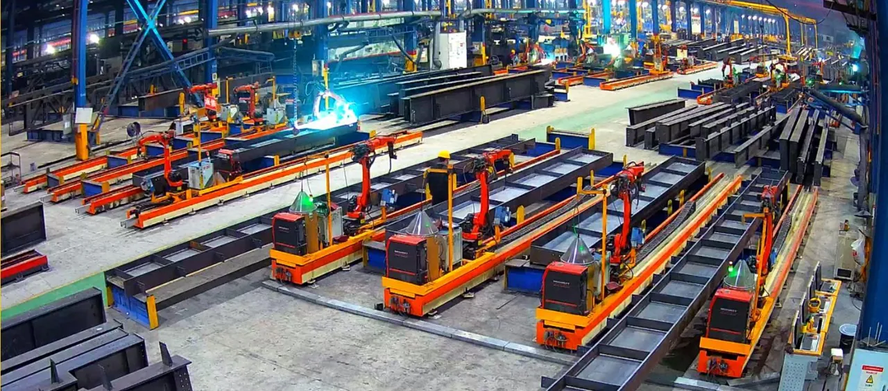
The layout of a welding robot station decides how the torch reaches each joint. For structural steel, the main choice is between a robot that travels beside the component, a robot suspended above it and robots mounted beneath a gantry frame.
Start With the Workpiece, Not the Axis Count
Axis count describes how the robot and its carriage or supporting structure move. On its own, it does not show whether the torch can reach a particular weld. Two components of similar size can present very different access once stiffeners, brackets and fixtures are in place.
Begin with a representative part: its length and width, the joints that need welding, the surrounding steelwork and how the part is supported and loaded.
Rail-Mounted Welding Robots
A ground-rail layout places the robot on a travelling carriage alongside the component. The carriage moves the robot along long members while the arm positions the torch at each accessible joint.
Typical work includes H-section columns, roof beams, crane runway beams, corbels and purlin brackets with relatively open geometry. On the 7-axis station, the supported forms include straight, planar polyline and vertical fillet welds.
Cantilever Welding Robots
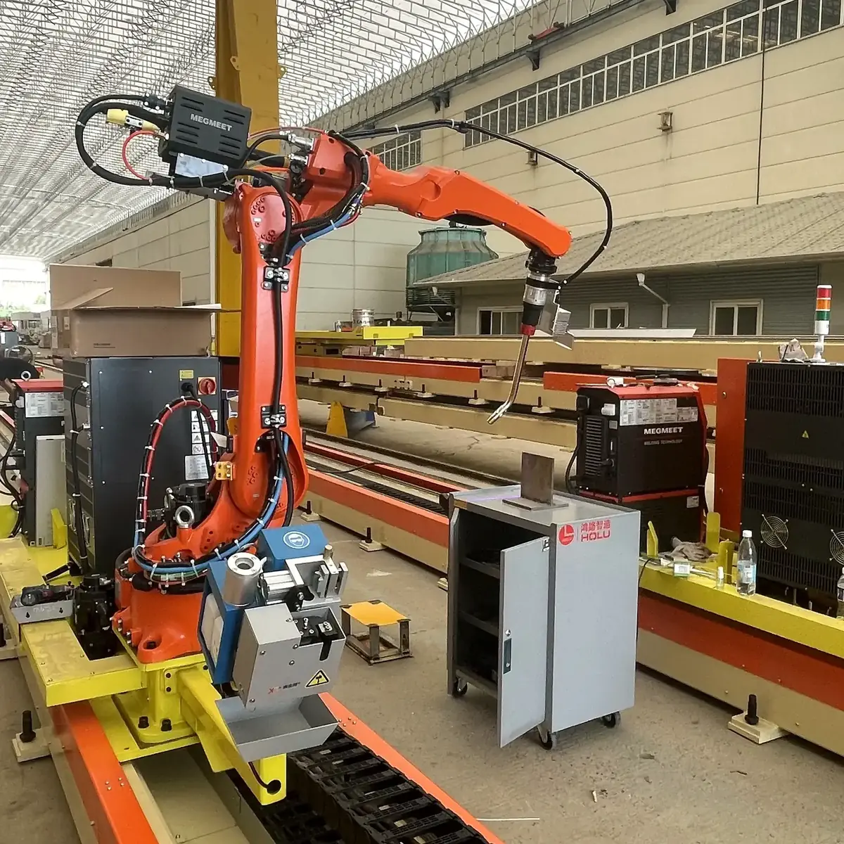
A cantilever layout suspends the robot beneath a supporting structure above the work area. It is aimed at bridge steel, plate-unit diaphragms and other wide planar components where welds are spread across a plate assembly.
Stiffener height and spacing, plate openings and joint orientation shape the torch approach. A 9-axis inverted cantilever arrangement serves a different application: three-dimensional frames and box structures.
Gantry, Fixed-Base and Trolley Layouts
Gantry systems place one or more inverted-mounted robots beneath a frame that spans the work area; workpiece position and access beneath the frame shape the layout. A fixed-base workstation keeps the robot at a stationary mounting point and relies on workpiece positioning to present each joint.
For large, irregular or hard-to-move components, a compact robot and welding equipment on a transport trolley can be brought to the task.
Comparison at a Glance
| Layout | Robot arrangement | Typical structural steel work | What to check |
|---|---|---|---|
| Rail-mounted | Robot on a travelling ground-rail carriage beside the part | Long beams and columns with relatively open joints | Access around brackets and stiffeners; loading space beside the rail |
| Cantilever | Robot suspended beneath a cantilever structure | Bridge steel, plate-unit diaphragms and wide planar components | Stiffener height and spacing; approach to enclosed details |
| Gantry | Inverted-mounted robots beneath a frame spanning the work area | Parts positioned beneath the frame | Access beneath the frame; handling route |
| Fixed-base | Robot at a stationary mounting point | Parts that can be positioned at the station | How the part is positioned to present each joint |
Read the welding robot FAQ6, 7, 8 or 9-axis welding robots explained
Questions to Answer Before Choosing
How long and wide are the parts?
Long members favour travel along the part; welds spread across a wide plate assembly point towards an overhead approach.
Where are the difficult joints?
Enclosed details, closely spaced stiffeners and attachments often decide the layout more than the open welds do.
How do parts arrive and leave?
Crane routes, supports and the next operation need space alongside the robot’s working area.
Is there a 3D model?
Model-based preparation needs a model that matches the assembled part. Scan-based reverse modelling is currently limited to flat web plates with stiffeners.
Get a Layout Recommendation
Send a description or photo of a representative part and the welds you want to automate. We review the joints and working space and suggest which layout merits further discussion.
Or email [email protected]